Ready for the future? Take off into the world of power electronics with your ticket – full of innovations, trends, and new impulses. Secure your ticket now:
Bi-Directional Switches Enable Soft-Switching AC Converters
6 May 2025
According to Michael Harrison, Senior Power Electronics Architect at Enphase Energy, monolithically integrated bi-directional GaN HEMTs have the potential to revolutionise power conversion.
Bidirectional power switches (BDS) are not a new invention; cycloconverters (which can convert alternating current to direct current, direct current to alternating current, or alternating current of one frequency or voltage to another alternating voltage) have been working with BDS for some time. BDS based cycloconverters existed long before power semiconductors. »The earliest documented cycloconverter design was by Louis A. Hazeltine of General Electric in 1923,« explains Harrison. Accordingly, the BDSs of that time also consisted of triodes, i.e. vacuum tubes. In 1980, the first transistor-based cycloconverters, also known as matrix converters, came onto the market. »However, these matrix converters are typically only used in large power converters above 100 kW; most of today’s AC/DC and DC/AC converter topologies are still hard-switched,« continues Harrison.
Hard switching – a switching process with high losses
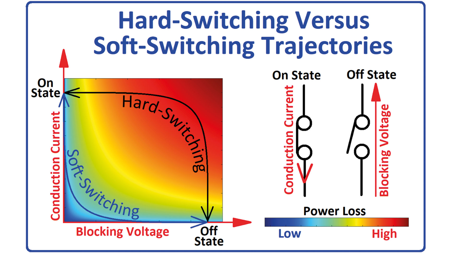
Hard-switched topologies use a diabatic switching process that causes a high current to flow through the power switch while simultaneously exposing it to a high blocking voltage. The result is significant switching losses.
With hard switching, the switch itself is responsible for commutation. The voltage applied to the inductor is changed abruptly – against the natural direction of the inductive current. In other words, the switching element uses brute force to act against the natural laws of physics, i.e. the natural behaviour of current flow, by forcing commutation in the opposite voltage direction. Harrison continues: »To minimise the switching losses that occur, engineers try to shorten the switching times, but this leads to extreme voltage dV/dt and current rise rates di/dt. And these fast transitions in turn cause significant electromagnetic interference.« So switching times are sometimes increased again, but at the expense of efficiency and additional heat dissipation costs.«
Soft switching – an adiabatic process
Figure 1: Hard and soft switching characteristics. Image Sources: Enphase Energy
In power electronics, the concept of adiabatic (loss-free or soft) switching can be achieved on the basis of two simple operating principles:
ZVS – turn on a switch only when no voltage is present across it.
ZCS – turn off a switch only when no current is flowing through it.
The practical implementation of soft switching (ZVS or ZCS) therefore requires a mechanism that operates independently of the actual power switch and is able to manipulate voltages and/or currents in the power converter circuit to control the switching operations. Today, »such a mechanism is typically implemented using simple reactive circuit elements, i.e. inductors and capacitors,« Harrison explains.
With this separate reactive circuit controlling the commutation, it is no longer necessary to use the switch itself to apply »brute force« to accomplish the commutation.
By decoupling the switching process from the switching element, »it is possible to deliberately slow down the switching processes and thus control the rates of change of voltage and current – dV/dt and di/dt. And this targeted control goes a long way to reducing the electromagnetic interference that typically occurs during fast, abrupt transitions,« continues Harrison. Soft-switched topologies also drastically minimize, if not eliminate, switching losses.
Harrison criticizes the fact that many converters today are marketed as soft-switched, but are only equipped with rudimentary soft-switching technology. »Soft-switching topologies also have benefits for equipment manufacturers, making it easier to meet regulatory efficiency standards and providing significant savings in cooling and EMC measures. In systems where heat dissipation is limited or strict EMC requirements must be met, soft-switched converters prove to be a cost-effective solution,« Harrison emphasizes.
Losses still remain
According to Harrison, even the best SMPS available today, which implement ZVS and ZCS circuits for all switches, for all switching states, and for all operating conditions, are not yet able to guarantee completely adiabatic (loss-free) operation at the system level. Losses due to conducting resistances, magnetic components, parasitic effects or control logic still remain. Harrison continues: »However, studies and practical experience show that with the consistent use of soft-switching techniques and appropriate system integration, overall efficiencies in excess of 99 percent are possible – a decisive step towards highly efficient, compact, and sustainable power converters«.
“The BDS device is the key enabler for achieving soft switching in AC input/output converters, a factor that has resulted in considerable research to determine the practical suitability of adopting BDS based power converter topologies for lower power applications.”
DC/DC converters are already capable of soft switching
PSFB (phase-shifted full-bridge) and LLC resonant converters are two common DC/DC converter topologies that rely to some extent on ZVS soft switching, according to Harrison. However, »both of these ZVS topologies are often used to implement an isolated converter in the second stage of an AC/DC power supply. The soft switching advantage of these ZVS topologies is inevitably weakened by the use of a hard-switched PFC boost converter in the first stage,« says Harrison. (PFC: Power Factor Correction)
Although the aforementioned converters are commonly used in DC/DC power conversion applications, there are very few examples of practical, scalable AC/DC or DC/AC converters using soft switching techniques. One exception is the use of ZVS in critical conduction mode (CrCM) PFC topologies for low power applications. But even here, Harrison explains that with this topology, achieving ZVS is directly linked to a deterioration in the current form factor (IRMS/IAVE).
No soft-switched topologies for AC/DC and DC/AC conversion
Harrison explains why there are still no practical, scalable AC/DC or DC/AC converters with soft switching technology: »In the PSFB and resonant LLC topologies, the inductor current reverses polarity at the converter switching frequency.« The polarity reversal is triggered by the reactive inductance of the transformer and/or the power inductor. In contrast, in conventional continuous inductor current AC/DC PFC converters and DC/AC inverters, the inductor current remains unipolar – it is amplitude modulated at the switching frequency, but changes polarity only at the much lower power line frequency. Harrison: »This unipolar current characteristic is the reason why conventional AC/DC and DC/AC converter topologies are not able to support soft switching techniques.«
»If you want to design an AC/DC or DC/AC converter whose inductor current changes polarity with the switching frequency, it’s clear that you need power switches that can control the current flow in the positive or negative direction while simultaneously blocking a voltage with positive or negative polarity, and a BDS meets that criteria. To me, they are the key technology that makes soft-switching AC/DC and DC/AC converters possible,« explains Harrison.
Semiconductor-based BDS
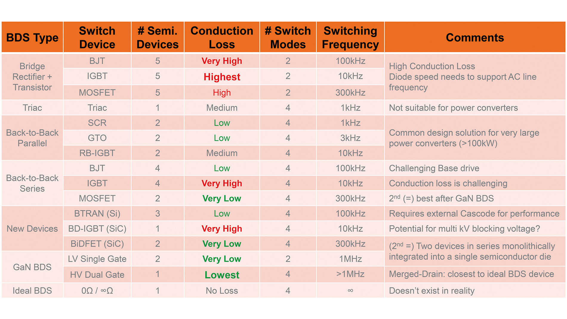
A simple BDS circuit – a UDS (UDS: Uni-Directional Switch) device is placed between the DC terminals of a full-bridge rectifier. However, the three series-connected semiconductor devices (two diodes and one UDS) result in high conduction losses, and only two switching states are supported: on and off.
The Triac – the Triac is currently the only commercially available monolithically integrated BDS. The disadvantage of Triacs is their high conduction loss, typically twice that of an SCR (thyristor). They are also sensitive to high voltage rise rates (dv/dt). As a result, Triacs are primarily used for line frequency-based power control of small ohmic loads (e.g., incandescent lamp dimmers and electric heater thermostats).
Parallel Back-to-Back BDS Pairs – in matrix converters (10 kW to 10 GW), two reverse-blocking UDSs are typically connected in a parallel back-to-back configuration. This configuration requires the use of reverse-blocking semiconductor devices such as SCRs and GTOs (gate turn-off thyristors). The advantage of this approach is low power dissipation, but the disadvantage is limited switching frequency (SCRs: 2x line frequency, GTOs: 1 to 4 kHz).
Serial Back-to-back BDS Pair – a serially connected back-to-back pair of UDS components has traditionally been the standard solution for BDS applications with low power consumption (less than 10 kW) and frequencies around 100 kHz. Typically, reverse-conducting UDS semiconductors such as BJTs, IGBTs or MOSFETs are used. BJTs (Power BJTs are an obsolete technology) and IGBTs require a fast anti-parallel diode between the emitter and collector to behave reverse-conducting, while MOSFETs have an intrinsic body diode. IGBT-based BDSs have high conduction losses compared to MOSFET variants, which is why MOSFET-based BDSs have been the preferred approach for use in low-power, high-frequency applications.
Modern BDS devices offer four switching states:
on (conducting for both current directions)
off (blocking for both voltage directions)
forward diode
reverse diode
These two additional diode states are essential for soft-switching converter topologies.
Monolithically integrated BDS
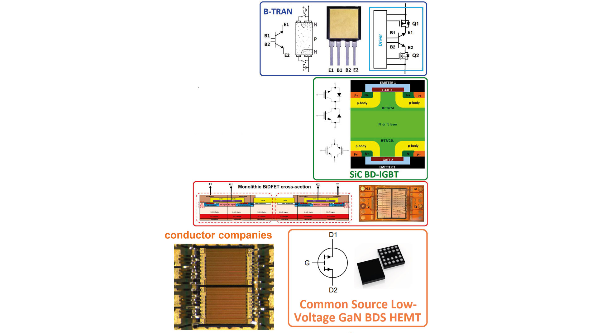
Over the past decade, there have been several research initiatives to develop new monolithically integrated power semiconductor BDS devices. The B-TRAN is based on a vertical silicon-based bipolar transistor structure, while the BD-IGBT is based on a vertical SiC (silicon carbide) IGBT structure. Both vertical approaches are complex in terms of wafer processing, packaging and cooling.
Another example is the SiC BiDFET – a monolithically integrated BDS based on two vertical SiC MOSFETs on the same semiconductor chip. Although the SiC BiDFET is a viable solution that is compatible with existing semiconductor processes, it does not offer any performance or cost advantages over the conventional series connection of two UDS components to create a composite BDS, other than the small potential cost savings of integrating two UDS components in one package.
In recent years, low-voltage (40 V) and high-voltage (650 V) monolithically integrated GaN HEMT-BDS devices have also been developed and commercialized. The low-voltage (40 V) variant uses a common-source single-gate implementation specifically designed for overcurrent protection of lithium-ion batteries. Three semiconductor manufacturers now offer such products. For the high voltage (650 V) variant with a merged drain architecture, devices based on three competing GaN HEMT technologies have been developed: gate injection transistor (GIT), Schottky gate HEMT and Cascode JFET. These three variants are also available from the manufacturers that developed them.
Figure 2: Latest developments in bi-directional switches B-TRAN, SiC BD-IGBT, SiC BiDFET
Figure 3: Comparison of semiconductor-based bidirectional switches
Lateral versus vertical
Conventional power semiconductors have a vertical structure with the source and drain on opposite sides of the chip, and the drain directly mounted to the package. This makes it difficult to add a second source and gate on what is normally the drain side of the chip. In addition, such components cannot be integrated into a package using existing packaging technology.
GaN HEMT devices are based on a lateral structure in which the gate, drain, and source are located on the same side of the chip. Current flow is through a 2D electron gas (2DEG) formed at the GaN/AlGaN interface. This lateral structure allows monolithic integration of a BDS by adding a second gate near the drain. This transforms the drain to become electrically equivalent to a second source, allowing current flow in both directions and blocking voltages in both polarities.
Fully JEDEC-certified, monolithically integrated GaN BDS devices are now available. This opens up opportunities for BDS topologies at lower power levels. One specific example: Enphase Energy is releasing the ninth-generation (IQ9) of its single-stage, series-resonant, bidirectional DC/AC cycloconverter topology microinverter. st