By Peter Gergely and Dr. Stefan Hain, onsemi
Introduction to DC Fast Charger Technology
As the automotive industry undergoes a transformative shift towards electrification, the demand for efficient and rapid charging solutions has never been more critical. DC Fast Chargers (DCFC) represent a pivotal technology in this evolution, enabling electric vehicles (EVs) to recharge significantly faster than traditional AC chargers. It further outlines the importance of the upcoming 100KW DC Fast Charger Unit, emphasizing its technological advantages, market relevance, and strategic positioning within the power semiconductor sector.
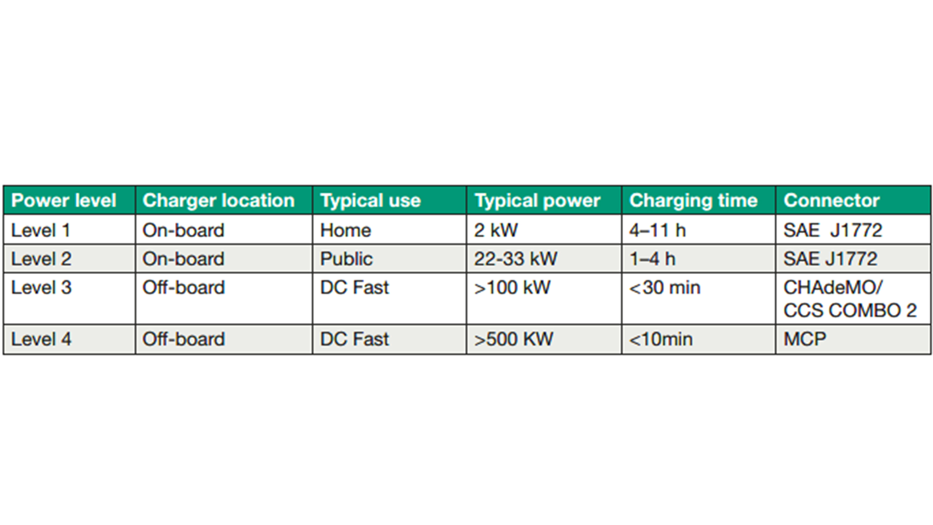
Based on their power ratings EV battery chargers can be divided into level 1, level 2 and level 3. Table 1 summarizes the characteristics of the three different power levels.
Onsemi’s 100 kW DC Fast Charger is designed for Level 3 and level 4 applications, specifically tailored for both unidirectional and bidirectional power flows. Bidirectional capability enables grid-to-vehicle (G2V) and vehicle-to-grid (V2G) interactions, allowing EVs to act as supplementary power sources during peak load or in emergency scenarios, enhancing the resilience of the energy grid.
System Architecture and Compliance
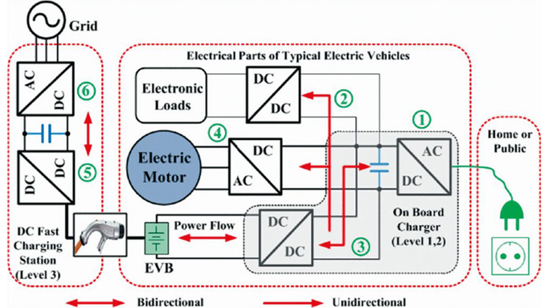
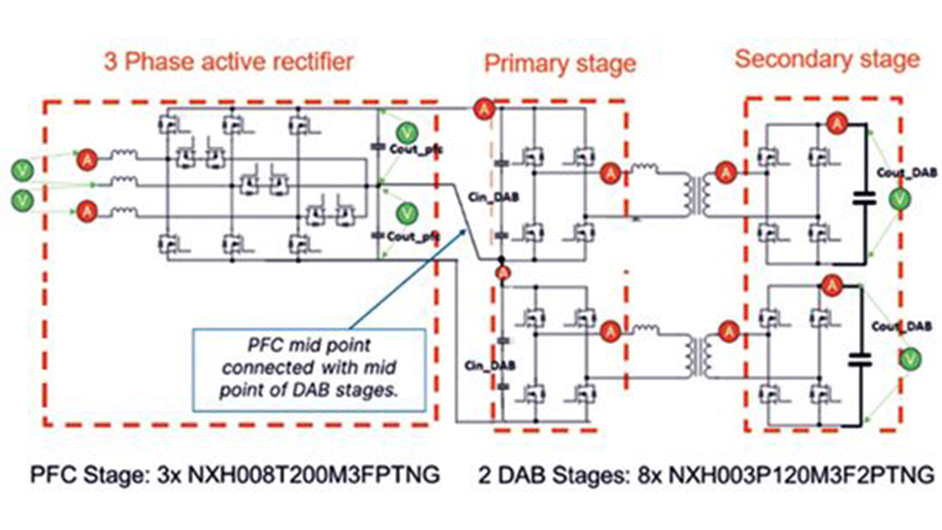
The off-board DC Fast Charger system typically comprises a two-stage conversion process (Figure 1): an AC/DC converter that interfaces with the grid, followed by a DC/DC converter that directly charges the EV battery. These stages enable unidirectional or bidirectional energy flow, depending on the configuration and incorporate galvanic isolation between the AC and DC circuits to ensure safety and compliance with IEC EN 61851-23 standards. This off-board configuration, known as Electric Vehicle Supply.
The off-board charging system is most commonly composed of two stages: a grid-facing AC/DC converter followed by a DC/DC converter providing an interface to EV battery. Based on the converter topology, both stages can allow unidirectional or bidirectional power flow. Since it is mandatory to guarantee galvanic isolation between the AC supply circuit and the DC output circuit according to the IEC EN 61,851–23 standard. The off-board charging equipment is part of charging station system known as Electric Vehicle Supply Equipment (EVSE).
Market Analysis and positioning of 100 kW DC Fast Charger Unit
The Growing Need for DC Fast Charging Solutions
The rise of EVs is transforming charging expectations. Consumers and fleets demand convenience and minimal downtime, making DC fast chargers essential. Unlike AC chargers that take hours, DC fast chargers can deliver up to 80 percent charge in under 30 minutes - critical for commercial EVs, high-utilization fleets, and transit systems.
Technological Advancements in DC Fast Charging
- Direct Current (DC) Charging Mechanism: DC fast charging delivers DC power directly to the battery, bypassing onboard conversion for much higher power and faster charging - ideal for high-demand applications.
- Enhanced Power Levels with Advanced Semiconductors: 100 kW charger supports 400 V/800 V and future high-voltage platforms. SiC semiconductors enable high efficiency, power density, and reliability for commercial and public fast charging.
- Modular and Scalable Design: Modular 100 kW design allows easy scalability by adding power modules—ideal for growing urban, highway, and fleet charging needs.
Market Trends and Competitive Landscape
The global DC fast-charging market is poised for robust growth, fueled by several key trends:
- Surge in EV Adoption: Government mandates and subsidies drive rapid growth in fast-charging infrastructure, projected at 30 percent CAGR over the next decade, led by the U.S., Europe, and China.
- Technological Competition and Innovation: Companies race to develop ultra-fast chargers (>350 kW) for larger batteries and faster turnaround. Leaders like ABB, ChargePoint, and Tesla offer solutions compatible with emerging high-voltage EV platforms.
- Significant Investment in Infrastructure: Public and private funding for EV charging is accelerating. U.S. infrastructure law allocates billions for high-speed chargers, creating strong opportunities for 100 kW units in cities, highways, and fleet depots.
Market Size and Total Available Market (TAM)
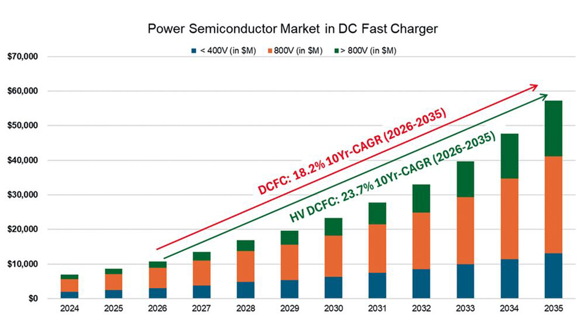
The DC fast charger market experienced a substantial expansion in recent years, with global installations reaching approximately 860,000 fast-charging units in 2023. The market’s value is expected to reach 17.6 billion dollars by 2023 and project further growth at a CAGR of around 30.9 percent from 2024 to 2032 (Figure 2). Additionally, research suggests that the market size for DC chargers could surpass 161.5 billion dollars by 2028, driven by advancements in power technology and growing EV adoption across sectors. In order to achieve this growth, the power semiconductor market for DC fast charger will have a CAGR of near to 23 percent in the next 10 years.
Power Range and Technology Trends
The charging infrastructure for electric vehicles is evolving rapidly. Modern fast-charging systems are now surpassing the 350 kW threshold to enable shorter charging times and meet the demands of heavy-duty EVs. A modular design with power units ranging from 25 to 150 kW ensures scalability and cost efficiency, allowing systems to adapt flexibly to different applications. Silicon carbide (SiC) semiconductors play a key role in this development. They deliver efficiencies above 98 percent, support high voltages, and provide exceptional reliability—critical factors for high-performance and durable chargers. In addition, bidirectional charging (Vehicle-to-Grid, V2G) is gaining momentum. This technology integrates EVs into the energy ecosystem by enabling them not only to draw power but also to feed it back into the grid. As a result, EVs contribute to grid stability and the efficient use of renewable energy.
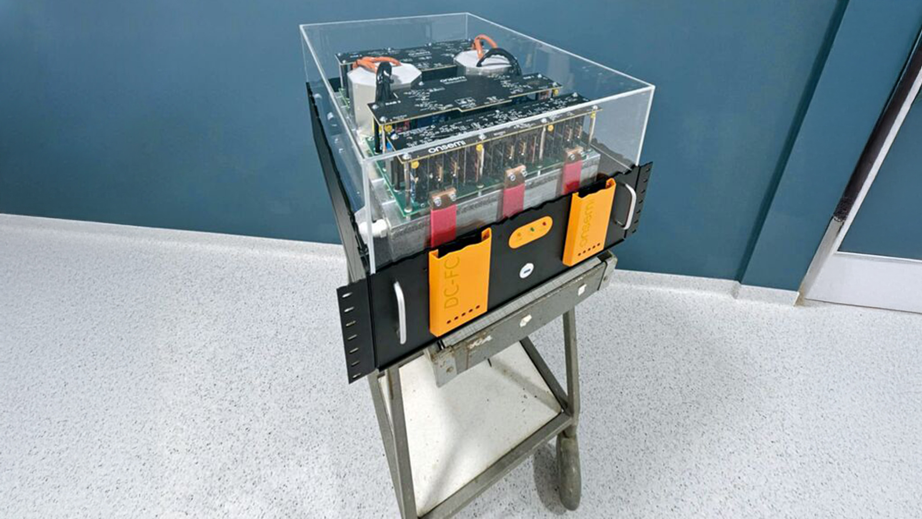
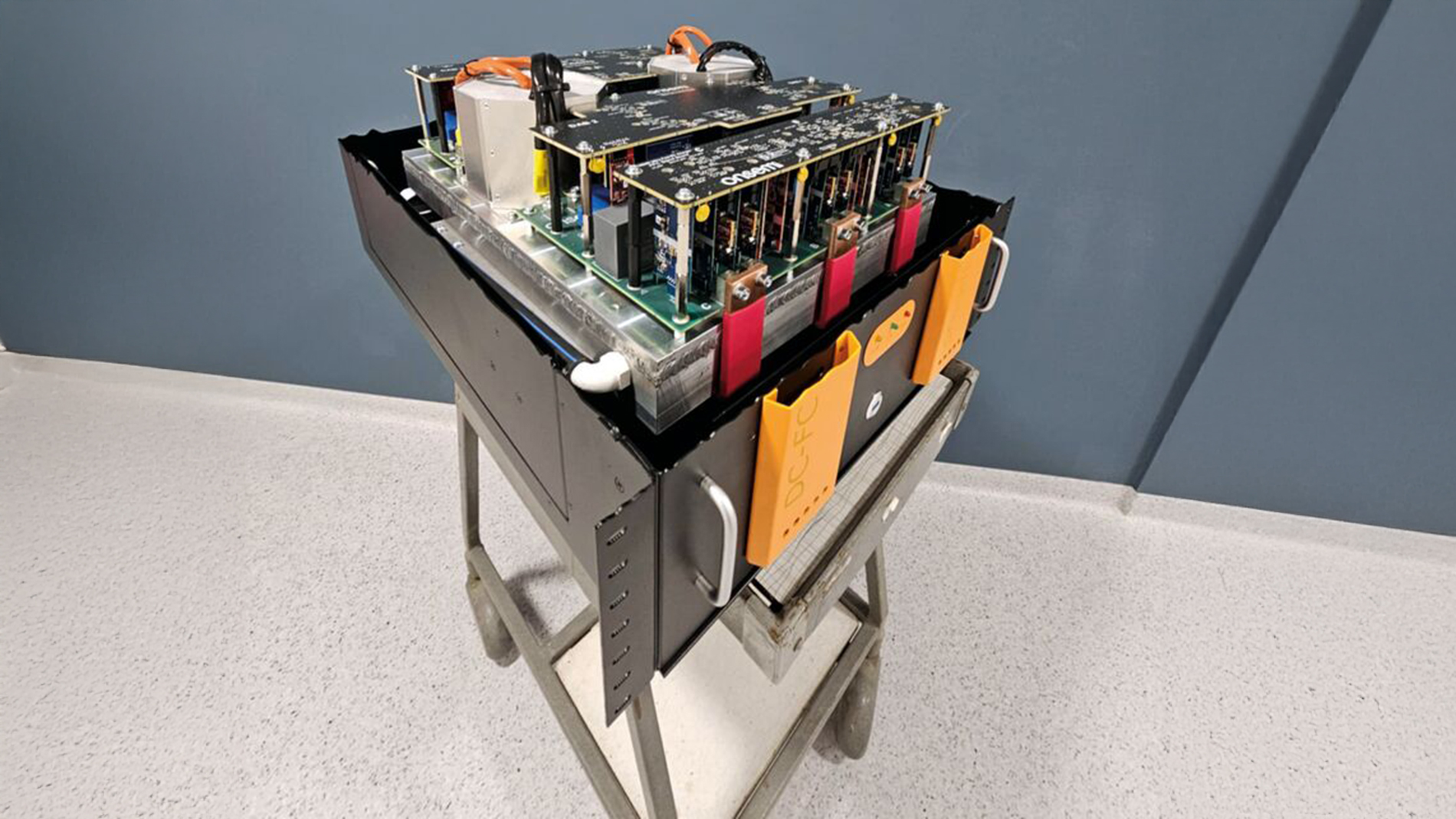
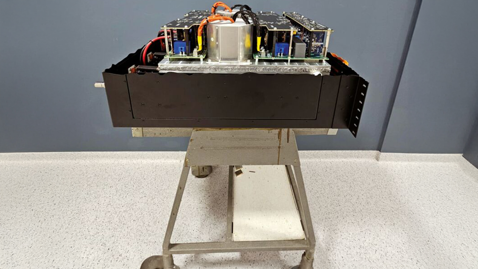
Final assembled system (Images: onsemi).
Future Trends in Charging Technology
Ultra-fast charging technology is entering a new era, with systems delivering more than 1 MW of power to enable near-instant charging for electric vehicles. This breakthrough dramatically reduces downtime and makes high-performance EVs viable for long-distance travel and commercial applications. Modern charging solutions are increasingly equipped with smart features such as real-time monitoring, predictive maintenance, and dynamic load balancing. These capabilities ensure optimal performance, minimize operational costs, and enhance reliability for both operators and users. Sustainability is also a key driver of innovation. Renewable energy integration, including solar- and wind-powered charging stations, is becoming a standard approach to reduce carbon footprints and lower energy costs. By combining ultra-fast charging with clean energy sources, the industry is paving the way for a greener and more efficient mobility ecosystem.
The onsemi Solution - Strategic Positioning of the 100 kW DC Fast Charger Unit
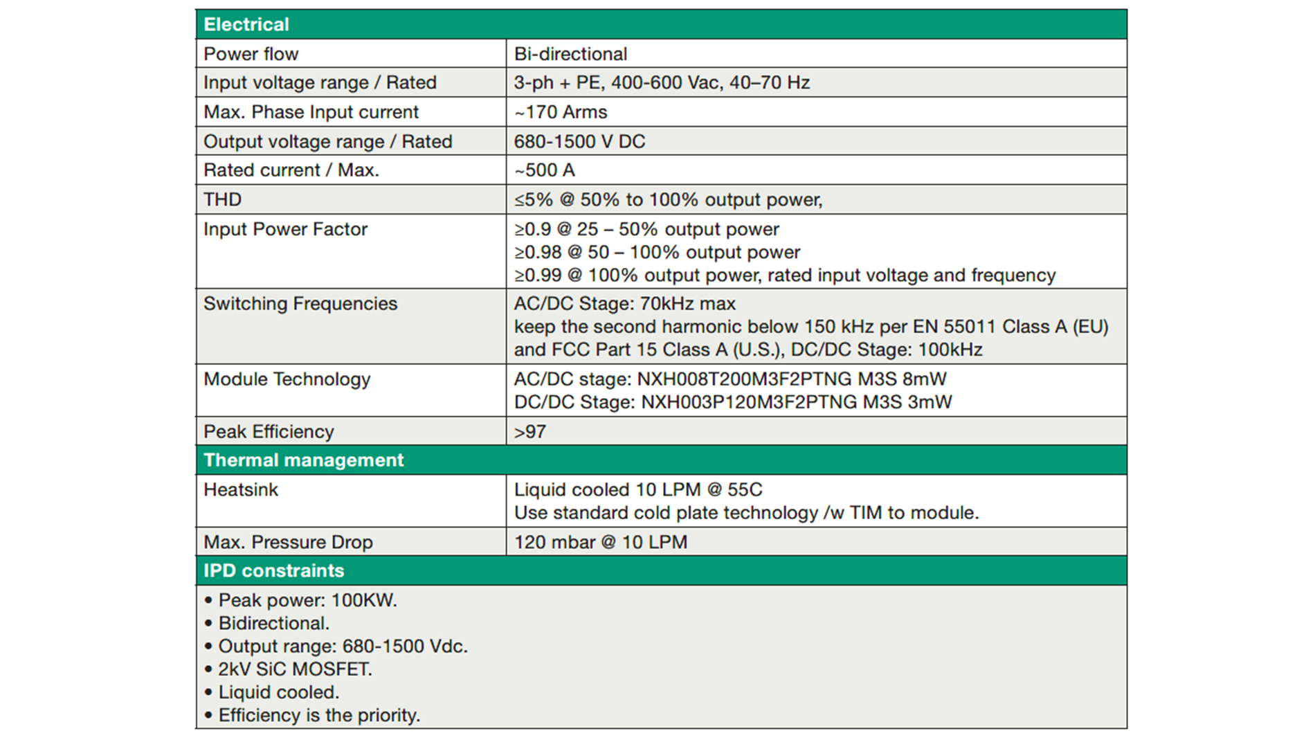
Onsemi’s 100 kW DC fast charger unit is strategically positioned to address the evolving demands of the EV charging market. With its high-power capabilities, advanced SiC-based power modules, and modular design, it aligns with the needs of urban, commercial, and high-traffic environments. This unit can serve diverse applications, from public charging networks to commercial fleet operations, ensuring rapid charging times and minimal downtime. By focusing on achieving high efficiency (above 97 percent at nominal operation) and enabling 1000 V to 1500 V DC out capability for the first time in the industry, the 100 kW DCFC unit positions onsemi as a frontrunner in a competitive market, ready to meet the charging needs of today and tomorrow.
Electrical hardware design and mechanical/thermal design
The DCFC system consists of a Power Factor Correction (PFC) stage and Dual Active Bridge (DAB) DC/DC stages. The PFC stage employs three SiC modules (NXH008T200M3F2PTNG) designed with 2 kV dies, while the DAB stage comprises two 50 kW units, each with four modules (NXH003P120M3F2PTNG). The top-level architecture targets maintaining the second harmonic below 150 kHz per EN 55011 Class A and FCC Part 15 Class A standards, with efficiency exceeding 97 percent as a key priority.
Based on the provided system architecture, the PCBA Power Board is designed into two boards:
- Primary PCBA Power board: PFC + Primary DAB
- Secondary PCBA Power board: Secondary DAB
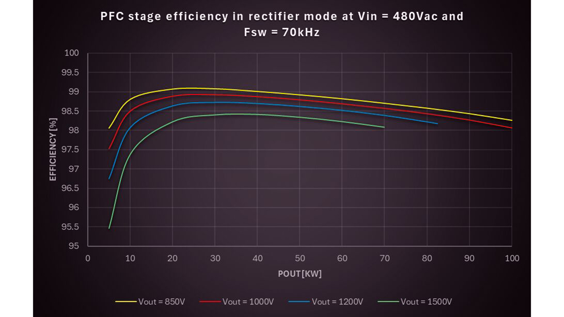
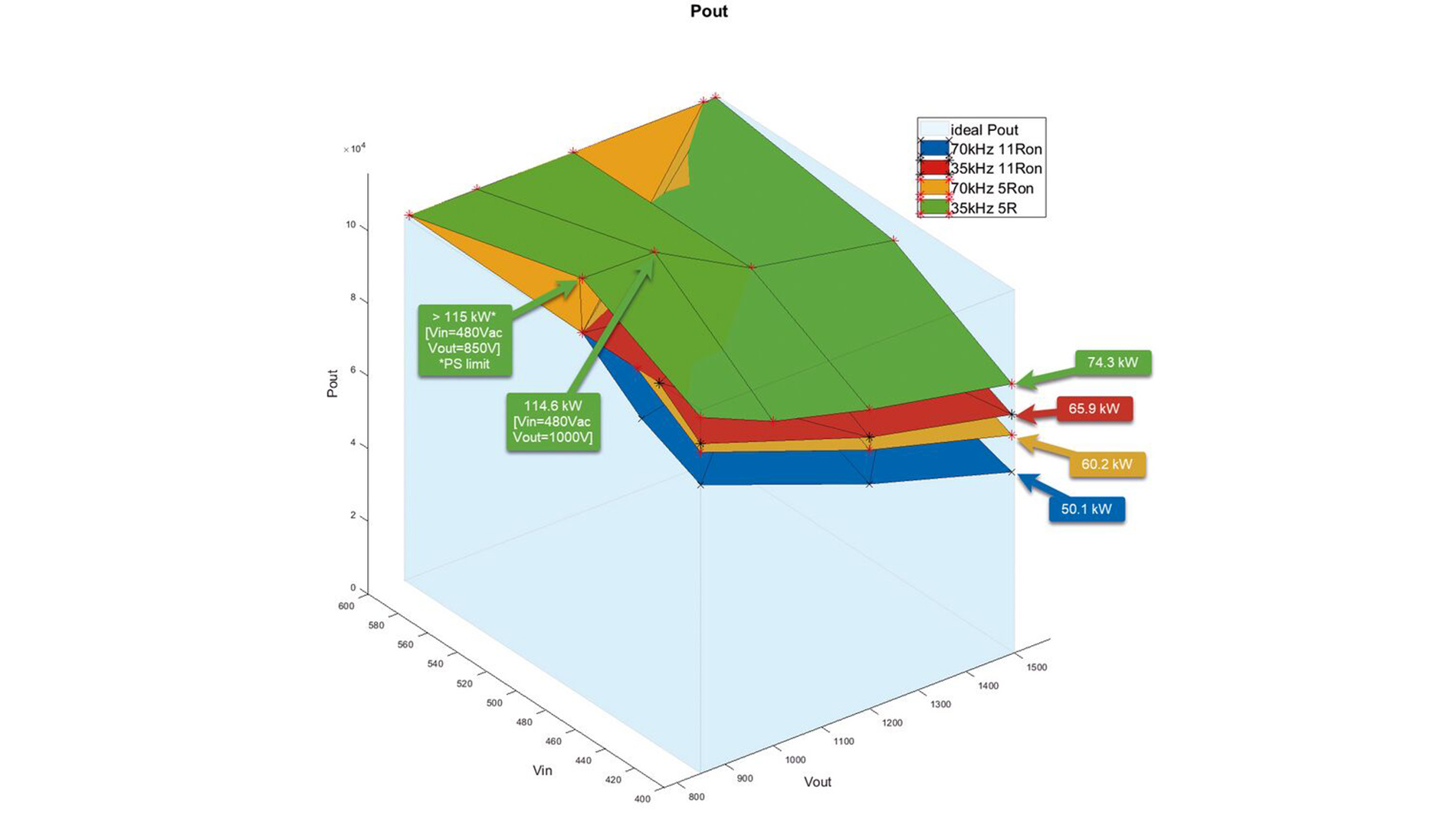
Total efficiency of PFC stage and different achieved power (Graphics: onsemi).
System assembly
The testing of the 100 kW DC fast charger power unit involves several stages, starting with the first article inspection (FAI) of individual boards to ensure component values and soldering quality are correct. This is followed by bring-up tests to verify the functionality of each board. The PFC stage commissioning includes assembling necessary components, preparing laboratory equipment, and testing the PFC in both inverter and rectifier modes while monitoring behavior and efficiency. The DAB stages commissioning will follow a similar process.
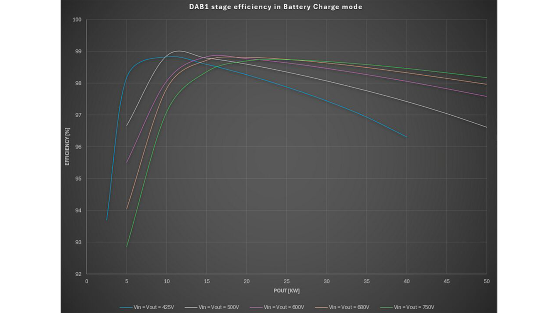
Total power loss and efficiency measurement result of DC/DC DAB at different power levels (Graphic: onsemi).
Test Plan and Commissioning Procedures
A detailed test plan validates electrical, thermal, and operational requirements of the 100 kW DCFC power unit. Testing encompasses mechanical and visual inspection, bring-up of individual boards, input power and AC/DC stage testing, DC/DC (DAB) stage commissioning, and integrated system performance evaluation. Tests include incremental load steps, voltage and frequency variations, efficiency measurements, fault and protection verification (over-current, over-voltage, under-voltage, thermal overload), and system integration using an external OPAL-RT OP4512 controller.
Key results of testing: PFC Stage Power Loss and Efficiency
The PFC stage Power loss and Efficiency measurement was performed to proof designed PFC stage performance. However, output power was limited by transistor’s Tj . Therefore the target output power of 100kW was not achieved for some combination of input and output voltages. Note:For measurement at Vin = 600Vac was Vout MIN increased to 860Vdc to keep PFC stage in boost mode. Vout MAX was decreased by 5V (from 1500Vdc to 1495V) due to limitation of used Power analyzer for all measurements.
DC/DC DAB Stage Results:
The Power loss and Efficiency measurement was performed to proof designed DAB stages performance. Each DAB stage was measured separately with maximum output power of 50 kW.
System Efficiency and Operating Modes
The DCFC operates bidirectionally in four modes combining battery charge or inverter operation with DAB stages connected either in parallel (for battery voltages 425–750 V) or series (850–1500 V). A “gray zone” between 750 V and 850 V allows operation in both configurations but outside ideal 1:1 voltage ratio mode, requiring efficiency evaluation for optimal setup.
Efficiency improvements are possible by adjusting gate resistor values once thermal and control algos are tuned.
_preview.jpg)
1. Battery Charge Mode - DABs series connection
Total measured efficiency of 100 kW DC fast charger system – DABs in series connection (Graphic: onsemi)
_preview.jpg)
2. Battery Charge Mode – DABs parallel connection
Total measured efficiendy of 100 kW DC Fast charger system – DABs in parallel connection (Graphic: onsemi)
_preview.jpg)
3. Inverter Mode – DABs parallel connection
Efficiency measurement results for system operation in inverter mode – DABs in series (Graphic: onsemi)
_preview.jpg)
4. Inverter Mode -DABs parallel connection
The performance at Battery Voltage 800 V and 850 V wasn´t measured because the middle point (DC_MIN) of the DC BUS voltage becomes unbalanced over V batt= 750 V (Graphic: onsemi)
Conclusion and Future Work
The 100 kW DCFC system was designed as a bidirectional charger. This means the charger is capable not only of charging a car battery from a 3-phase AC power supply but also of feeding the energy stored in the battery back into the AC grid. To achieve a wide range of battery voltage (from 425 V to 1500 V) while maintaining high efficiency, it was necessary to divide the DC-DC converter into two separate units, each with a nominal power of half of the total rated output. To reach the total desired power output of the charger, these two DC-DC converters are connected either in parallel (for lower battery voltages from 425 V to 750 V) or in series (for higher battery voltages from 850 V to 1500 V).
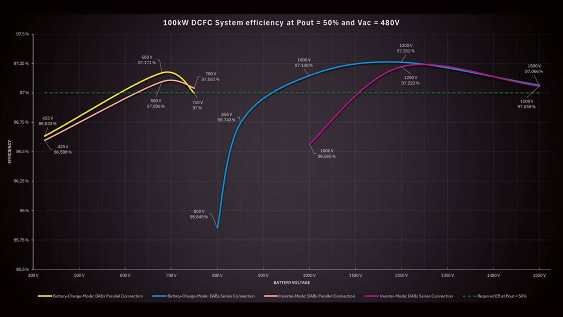
The figure on the right shows the measured energy transfer efficiency of the entire 100 kW DCFC system in all four operating modes, at an output power of 50 kW and an AC grid voltage of 480 V (phase-to-phase). As seen in the figure, the measured efficiency values are favorable and, in most measurement points, exceed the required minimum efficiency (indicated by a green dashed line).
Note: We can further improve system efficiency through reducing the gate resistors values of SiC modules (DAB and PFC).
The 100 kW DCFC demonstrator presents a robust design integrating advanced SiC modules, precise measurement and control, and a comprehensive test plan. Current limitations due to thermal management (both in PFC SiC module and DAB transformer) and control algorithm stability highlight areas for improvement. Mechanical optimization could reduce size and weight by 25–30 percent. Further work will determine continuation and refinement of the project to meet the full performance goals. eg
100 kW DC Fast Charger total system efficiency at 50 percent power and VAC 480 V (Graphic: onsemi).