By Dusan Graovac, Peter Luniewski, Holger Müller and Mark Münzer, Infineon Technologies
Kilometer per hour: An important metric beyond top speed
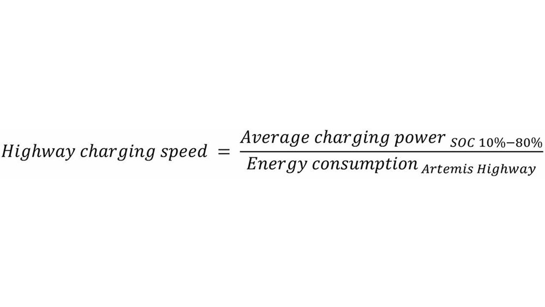
Market surveys on electromobility regularly show that range and charging time are crucial factors for customer satisfaction. Looking at the motivation behind these statements, it becomes clear that people are concerned on how a battery-electric vehicle will perform on driving distances that exceed the range of a single charge. A good indicator for long-haul performance in this context is the charging speed relevant for driving on a highway. To calculate this key performance indicator, the average charging power when charging from ten to eighty percent is divided by the energy consumption when driving on a highway; for instance, the energy consumption for the Artemis Highway. The result can be interpreted as the distance of highway driving, which could be recharged within one hour.
Electric vehicles deliver the best performance when fast charging is combined with energy-efficient driving. Today, depending on the vehicle size, values of up to 1500 kilometers per hour can be achieved. To illustrate how different levers in powertrain design influence highway charging speed (HWYCS), a reference vehicle is used in the following sections. The vehicle specification is defined to ensure equivalent output power at the motor shaft (Pout_mech = 250 kW) and identical energy demand for highway driving excluding powertrain losses (EHWY_w/o_PWT = 17.2 kWh).
Fast charging: A key driver for 800 V architectures
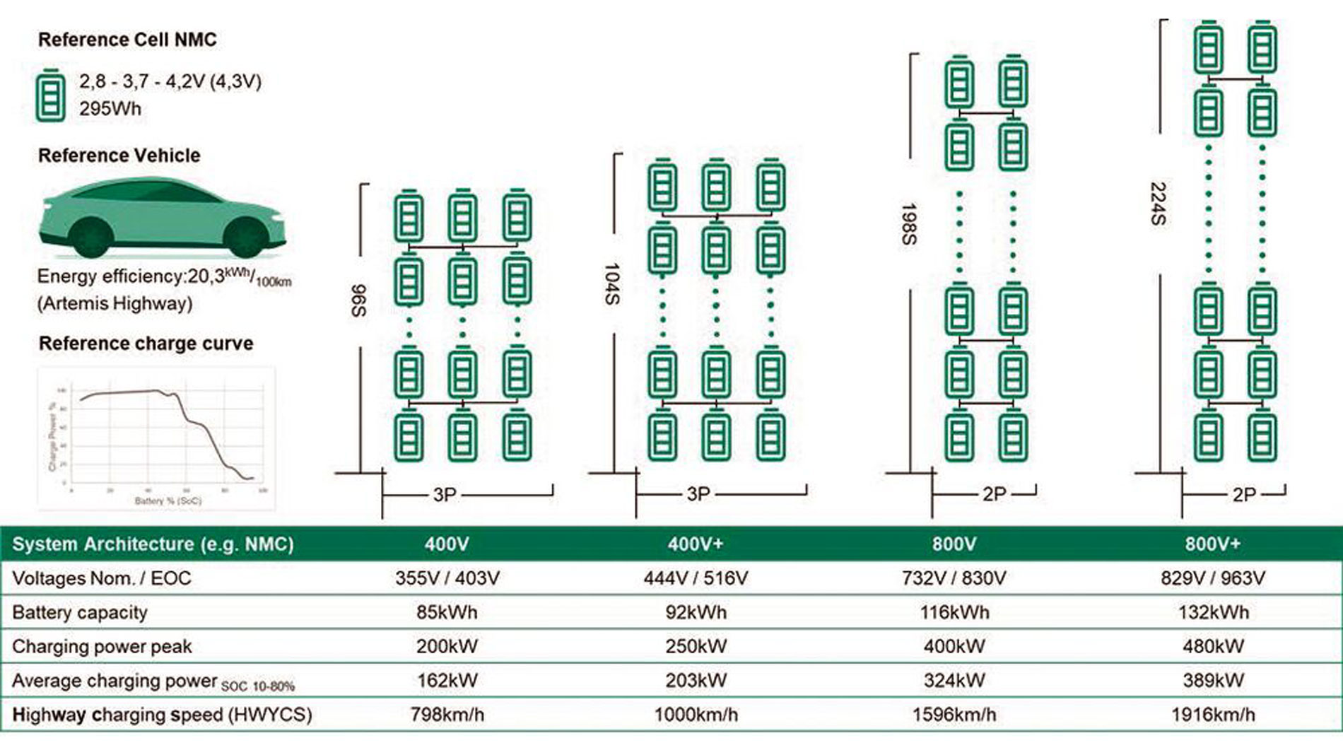
To provide sufficient battery capacity for long-distance driving, a high number of cells is required, allowing designers to arrange them in various series and parallel configurations. Once the necessary discharge and charge currents can be provided, it is beneficial to stack cells in serial connection. High c-rates of modern battery cells of up to five c for charging and ten c for discharging allow for high battery currents with limited cells switched in parallel. Still, charging currents of electric vehicles are limited by cables and plugs. Reducing charging time therefore is linked to increasing the number of serial connections. For example, charging at 400 V using uncooled cables with a CCS plug is typically limited to 250 kW. Options such as cable cooling or double-gun charging could increase this limit. However, by doubling the system voltage, currents can be maintained while providing up to 400 kW. This not only justifies the shift from 400 to 800 V systems but also explains the trend toward even higher voltage.
While the first generation of 800 V architectures operated with nominal voltages of around 725 V and reached end-of-charge voltages of up to 835 V, today’s systems are designed for nominal voltages of up to 850 V and end-of-charge voltages of 975 V. To remain compatible with low-voltage system standards, fast chargers capable of 1000 VDC have already been developed. The trend toward higher end-of-charge voltages is also observable in 400 V systems. Figure 1 shows representative battery configurations and how they perform in terms of maximum charging speed.
Assuming an equivalent powertrain efficiency, maximizing the voltage rating of an 800 V system can improve charging speed by more than twenty percent. While the benefit for charging is clear, higher battery voltages create new challenges. The entire powertrain must be designed to handle the elevated voltage ratings.
Energy efficiency improvements in 2L-traction inverters
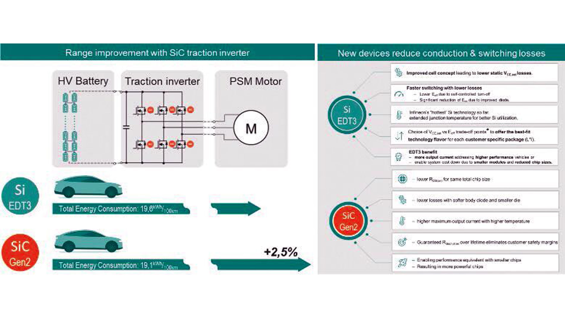
The majority of 800 V battery-electric vehicles on the market combine a permanent magnet synchronous motor with a two-level voltage-source inverter for the powertrain (Fig. 2). With the introduction of 1200 V SiC MOSFETs in the powertrain, vehicle range for highway driving has been increased by nearly three percent compared to previous Si IGBT-based vehicles.
To fully exploit the additional charging speed benefits of higher system voltages, the powertrain must be adapted to the new boundary conditions. For a proper analysis, the shift in the voltage profile associated with the maximum voltage needs to be considered. Figure 3 shows an example of how voltage profiles are scaled due to a higher end-of-charge voltage.
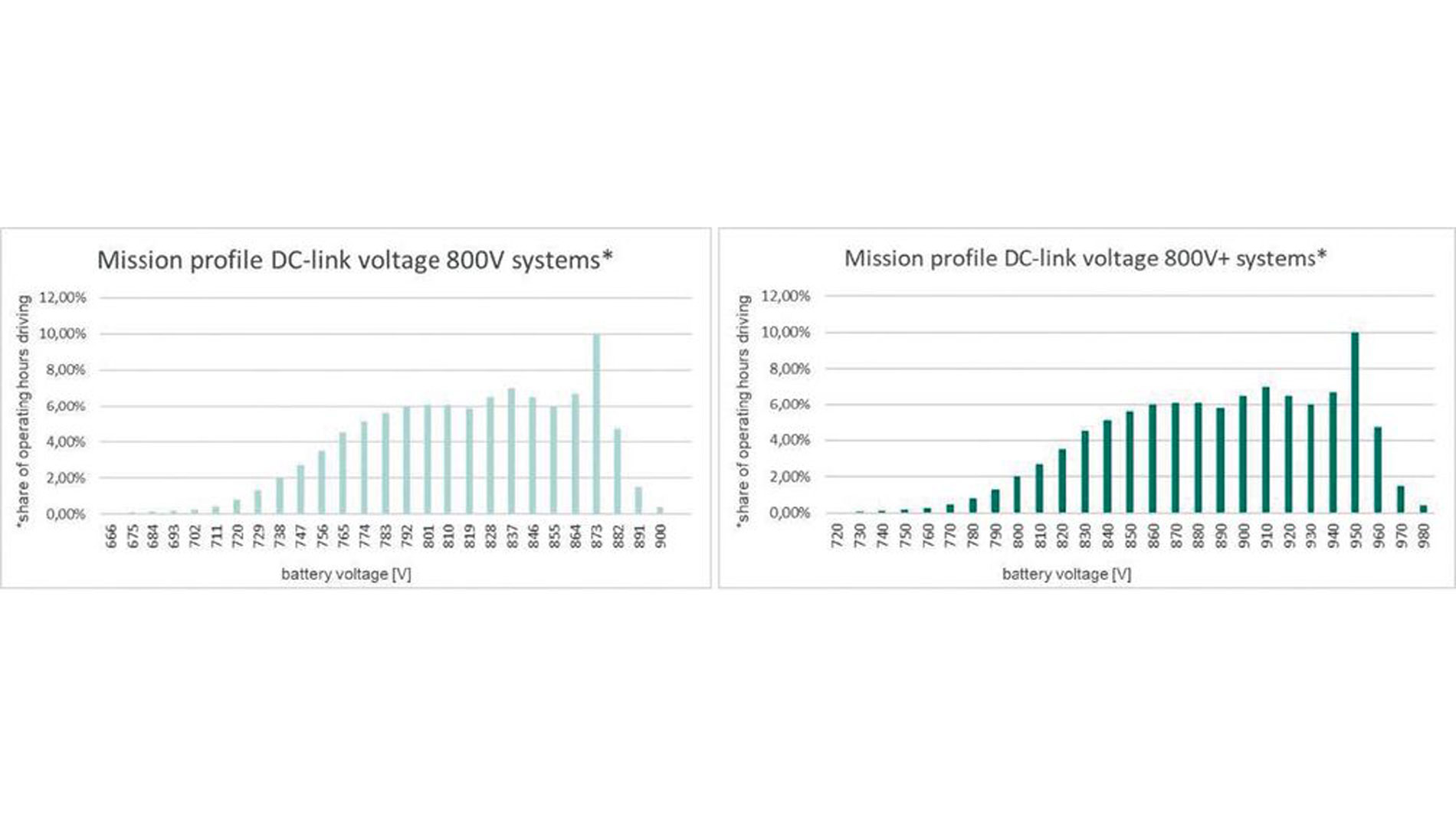
As vehicle performance requirements remain constant, the increased voltages can be used to optimize the system and reduce output currents by up to 12 percent (e.g., IRMS_800V = 530 A → IRMS_800V+ = 470 A). For an 800 V system, it is common industry practice to use 1200 V-rated power semiconductor devices. During the development of CoolSiC Gen2, Infineon anticipated the future trend toward more demanding voltage profiles by offering different device variants. For inverter designs investing in low stray inductance or a system with lower current requirements, Gen2pE is offered with a specified breakdown voltage of 1200 V. To allow higher power levels with average stray inductance values, Gen2 has been developed and qualified to guarantee voltages of up to 1400 V for transient overshoots. The additional voltage rating not only compensates for the increased system voltages but also enables faster switching. In combination with state-of-the-art packages and inverter designs, voltage slopes exceeding 20 kV/µs are possible. Figure 4 shows an example of how these different voltage ratings can be utilized in a traction inverter during turn-off.
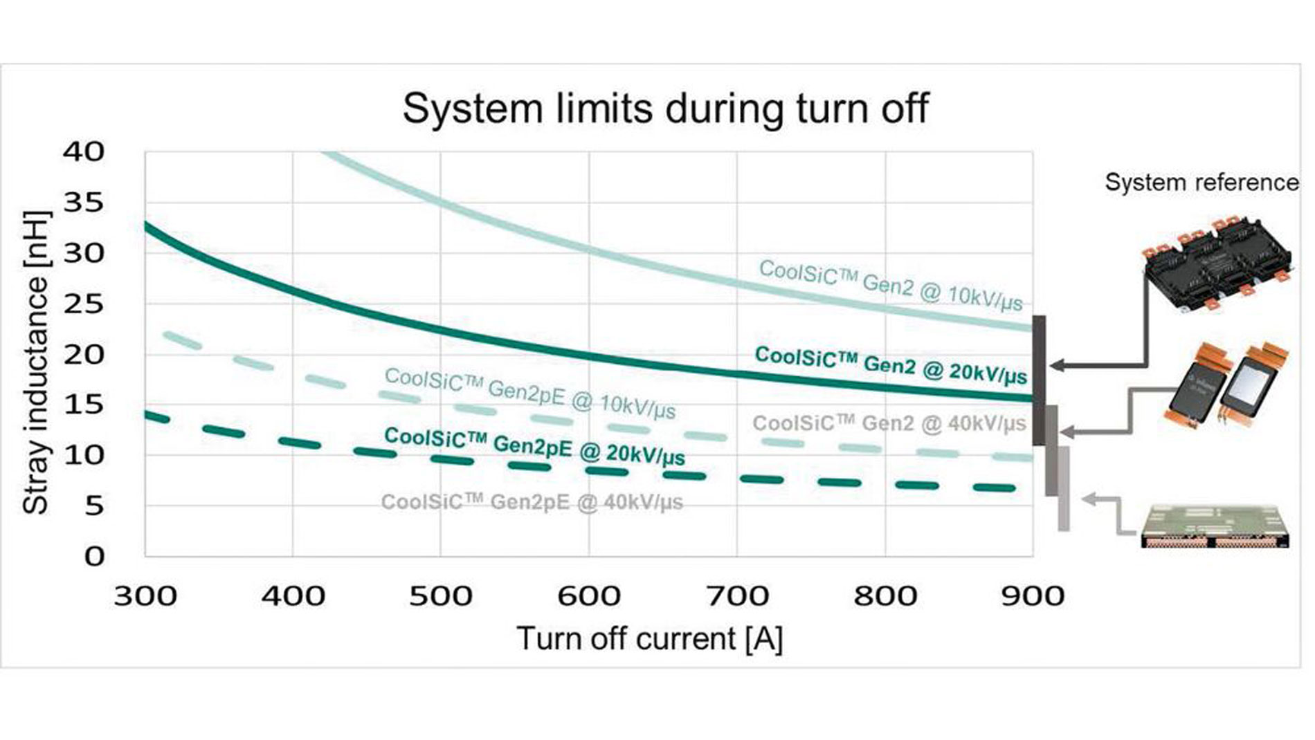
Optimizing switching speed through the selection of gate resistance is an integral part of every inverter design. The primary goal of this optimization is to reduce switching losses while ensuring compliance with the voltage ratings of the employed semiconductors. The chart depicts the maximum voltage slope that can be managed when switching off a peak current (x-axis) in a system with a defined stray inductance (y-axis) at a DC-link voltage of 1000 V. Solid lines correspond to a 1400 V overvoltage limit, while the dashed lines represent a 1200 V limit. Integrated in the chart are representative stray inductance values for inverters build from different power package concept. For a 250kW traction inverter with an 800V+ battery configuration currents of up to 665 A need to be turned off safely. According to figure 4 a design with classical frame modules and a system stray inductance of 18nH could be switched with 20kV/µs when using CooolSiC Gen2. An alternative would be to design an inverter with chip embedding and a stray inductance of <8 nH based on CoolSiC Gen2p. For each package, CoolSiC technology is available, allowing faster switching and consequently reducing switching losses. The importance of low switching losses for highway performance is illustrated in Figure 5.
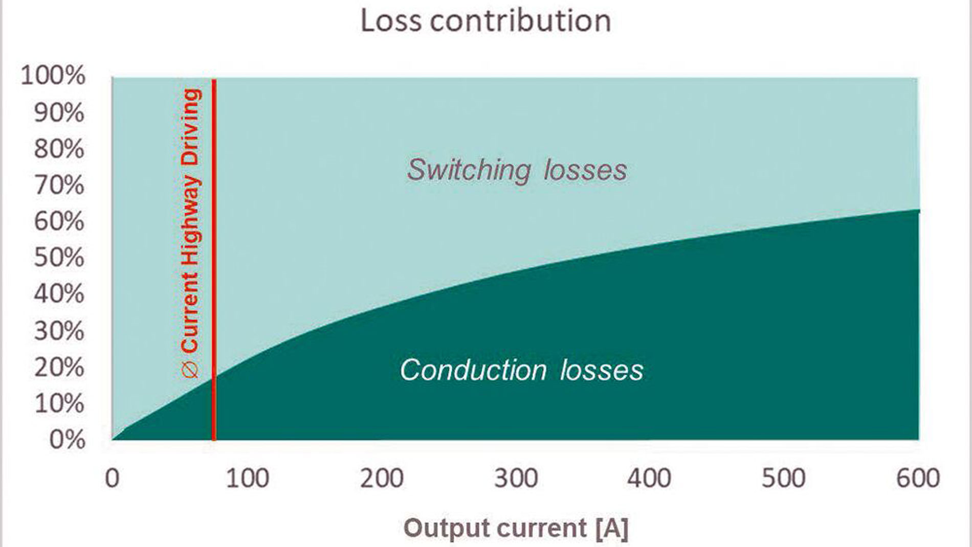
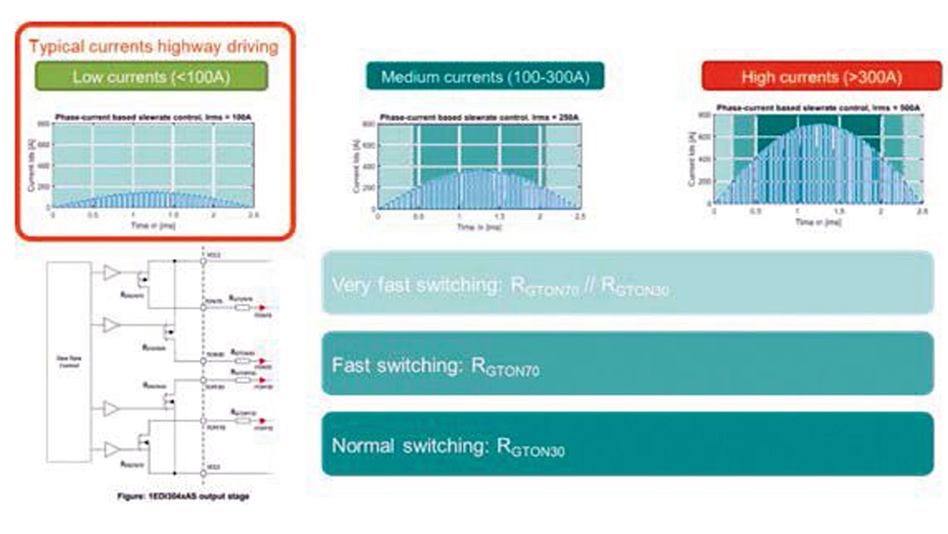
Since switching losses account for more than 80 percent of inverter losses when driving on the highway, reducing these losses has a significant impact on overall energy consumption. Doubling the switching speed from 10 to 20 kV/µs reduces the switching losses by approximately 30 percent. In combination with the lower output currents of an 800 V+ system, total losses can be reduced by more than 20 percent compared to conventional 800 V systems. Further switching loss improvements can be achieved by implementing gate drivers with a slew rate control functionality, such as the EiceDRIVER 1EDI304xAS.
To optimize switching losses, the output stage of these drivers is adapted on the fly. At low currents, when overvoltage is not critical, the drivers switch the SiC MOSFET faster than during full-power operation. As figure 6 indicates the output stage of a slope control driver has two separate output stages for turn on and turn off. Via the control interface either of them or both can be switched. When switching both in parallel the lowest switching losses can be achieved. Most of the time during a highway driving the currents are low enough to take full advantage of such reduced switching losses of slope control. A traction inverter incorporating the suggested improvements will operate with more than 99 percent of efficiency, by which HWYCS will reach 1948 km/h.
Powertrain topologies targeting the next level of energy efficiency
The high efficiency of the traction inverter limits the potential for further improvement without a fundamental change. In the pursuit of additional reductions of powertrain losses, the impact of inverter currents on e-motor performance has been identified as a lever with significant potential. By introducing a three-level topology, the total harmonic distortion can be optimized.
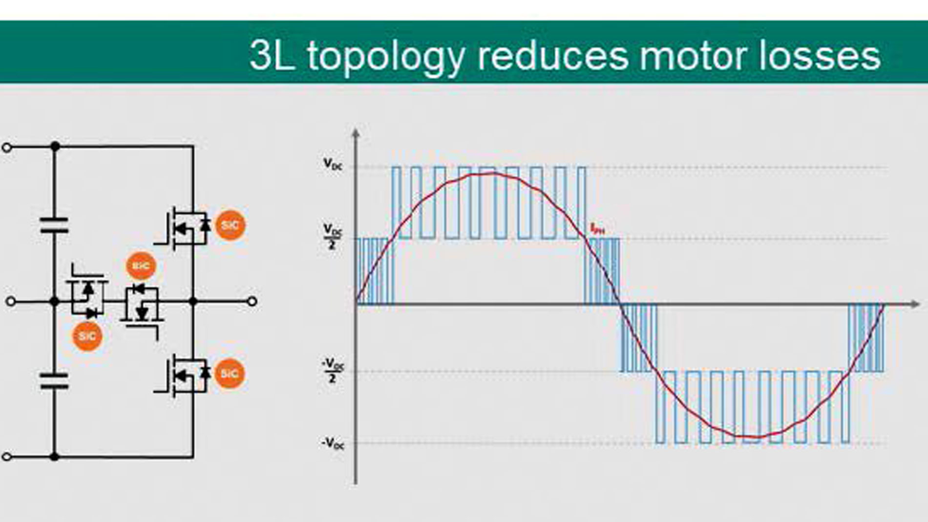
Figure 7 shows the circuitry of one phase of a T-type inverter, along with the corresponding output currents and voltages. In contrast to classical two-level inverters, the anti-parallel SiC switches in the middle leg of the T-type inverter allow the output phase to be connected to the neutral point. As a result, the new output waveforms reduce motor losses during highway driving. With multi-level inverters, HWYCS of more than 2026 km/h can be achieved.
Summary
800 V architectures are essential for increasing highway charging speeds, and their positive impact on charging performance is driving further increases in system voltage. The strong influence of switching losses during highway driving is addressed by new SiC MOSFET generations and low-inductive packages. Leveraging these new technologies, traction inverters can achieve efficiencies of more than 99 percent. Multi-level inverters represent the next step, as they improve motor performance. By combining all these technologies, the next generation of battery-electric vehicles will be capable of driving Shanghai-Beijing on the highway with a single charging stop of less than 15 minutes. eg
Authors
Dusan Graovac: With more than 20 years of experience, Dusan is a leading expert in EV powertrains.
Peter Luniewski: Peter´s focus is in power semiconductors for automotive power electronics.
Holger Müller: As an application engineer, Holger provides design-in support for power modules in traction inverters at industry-leading OEMs and Tier-1s worldwide.
Mark Münzer: As a Fellow for Motor Control Solutions Mark is responsible for system requirements and Trends of tomorrow’s EV powertrains