By Gerhard Stelzer, Senior Technical Editor at Würth Elektronik eiSos
Energy efficiency is important for conserving resources and protecting the environment. The more efficient the electronics in a car are, the greater the range of electric and hybrid vehicles. The same applies to conventional combustion engines. Given the extensive electrification of cars today with innumerable devices connected to the on-board power grid, it is worthwhile to use energy-efficient components throughout the vehicle to significantly reduce energy consumption.
The basis for energy-efficient components is largely laid by advanced power electronics. Whereas linear regulators used to be the most commonly used voltage regulators, switching regulators are now predominantly found in modern power electronics circuits. A few years ago, switching frequencies of up to 300 kHz were very common, but today, modern switching regulators based on GaN and SiC transistors are usually clocked at frequencies in the MHz range. In this high frequency range, switching losses and the losses of the storage choke are important aspects in the design of switching regulators.
In addition to energy efficiency, increasing energy demand is also playing an increasingly important role. Electronic devices in a modern car are becoming more complex and capable, but conversely also require more powerful power supplies. This means that switching regulators must deliver ever higher currents and, as a result, the power inductors must also have a significantly higher current carrying capacity. Achieving this performance is made more difficult by the additional trend toward miniaturization, such as in confined spaces in cars. Switching regulators must become smaller and more compact, but still deliver the same or even higher performance with reduced volume. This means that the requirements for the power density of the inductor are increasing.
To meet these requirements, research is continuously being conducted into new material mixtures from the iron alloy group to further reduce core material losses for high-current storage chokes. Based on this, the new WE-MXGI series was developed, which combines the best possible power density and current carrying capacity with the lowest RDC and minimal internal losses through innovative material selection and manufacturing technology. A new addition is the WE-MXGA power inductor family, which is specifically designed for use in automotive applications. Typical areas of application for the power inductors of the WE-MXGA family in vehicles are driver assistance systems, infotainment systems, body electronics, battery management systems, and DC/DC converters.
Automotive electronics developers are supported by the REDEXPERT online design platform, which allows the DC and AC losses of storage chokes to be determined with a level of accuracy that was previously unavailable. This is achieved by a metrology-based method that forms the foundation for core losses to be calculated much more accurately than would be possible with Steinmetz formulas.
WE-MXGA storage choke at a glance
The WE-MXGA storage choke is based on the latest and most innovative coil series from Würth Elektronik which have been fully tested and approved for the automotive market in terms of robustness. Of course, the WE-MXGA power inductors are qualified according to AEC-Q200 and allow operating temperatures from -40° to +125 °C. The WE-MXGA is currently available in two form factors: 5030 with inductance values from 0.22 to 15 µH and 4020 with 0.16 to 4.7 µH.
In conventional ferrite chokes, the copper enameled wire is usually wound around the core and soldered or welded to the terminal. The outer shield ring is then mounted and bonded to the inner core and the winding. The WE-MXGA belongs to the group of molded power inductors. The core powder consists of an innovative iron alloy which, in contrast to a ferrite choke, is pressed around the winding. This gives the WE-MXGA high inductance values in a small design. The special construction of the core also has a self-shielding effect.
The core material itself is temperature-stable, with no signs of thermal aging, as well as soft saturation behavior and low saturation drift over a wide temperature range. It also has high dielectric strength, which enables a working voltage specification of 80 V. An explanation of how Würth Elektronik defines the working voltage is described in App Note ANP126. To make the core resistant to environmental influences and rust formation, a protective layer is additionally applied to the surface.
Most of the pressed inductors available on the market still contain a termination clip to which the winding is welded. With the WE-MXGA, however, the winding is connected directly to the component’s connection pads using a direct contact method without soldering or welding. By eliminating the clip, the space within the core material is used optimally. This allows the coil diameter to be increased and a thicker copper wire to be used. This results in a significantly reduced DC resistance (RDC ) of the winding (Figure 1).
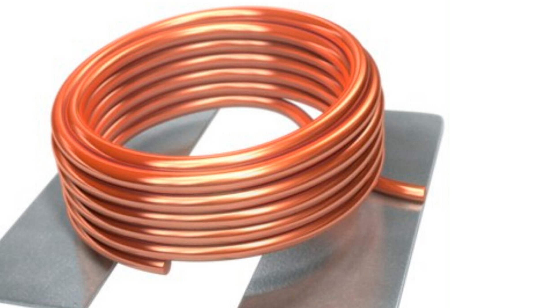
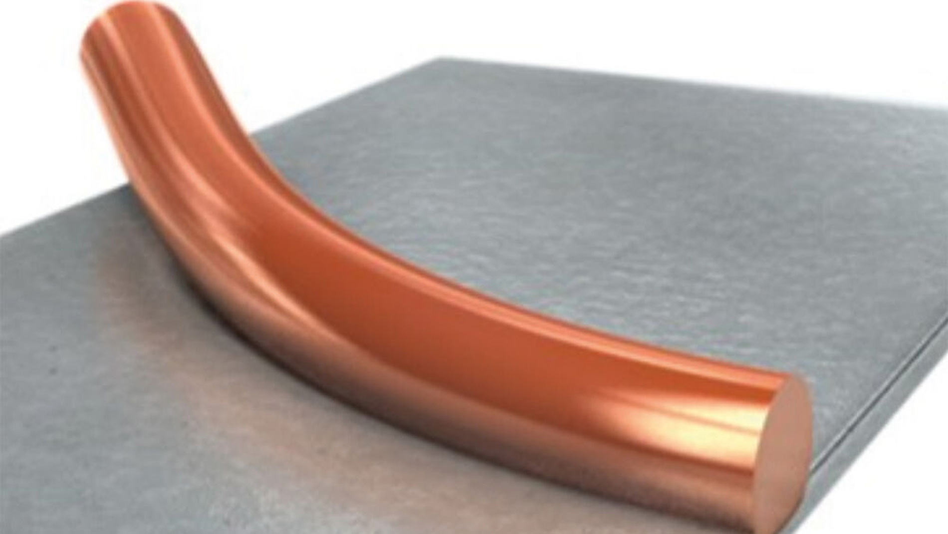
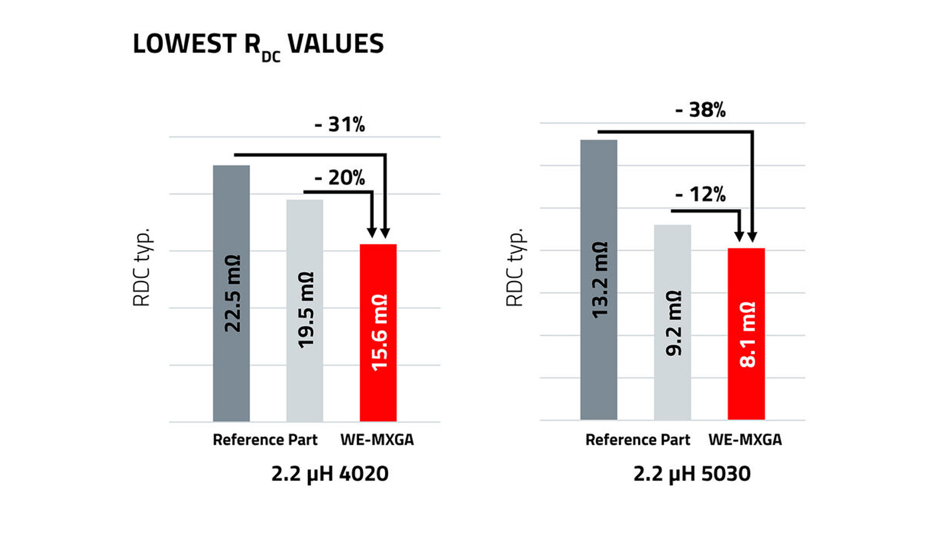
Figure 1: The direct contact method of the WE-MXGA enables low RDC values
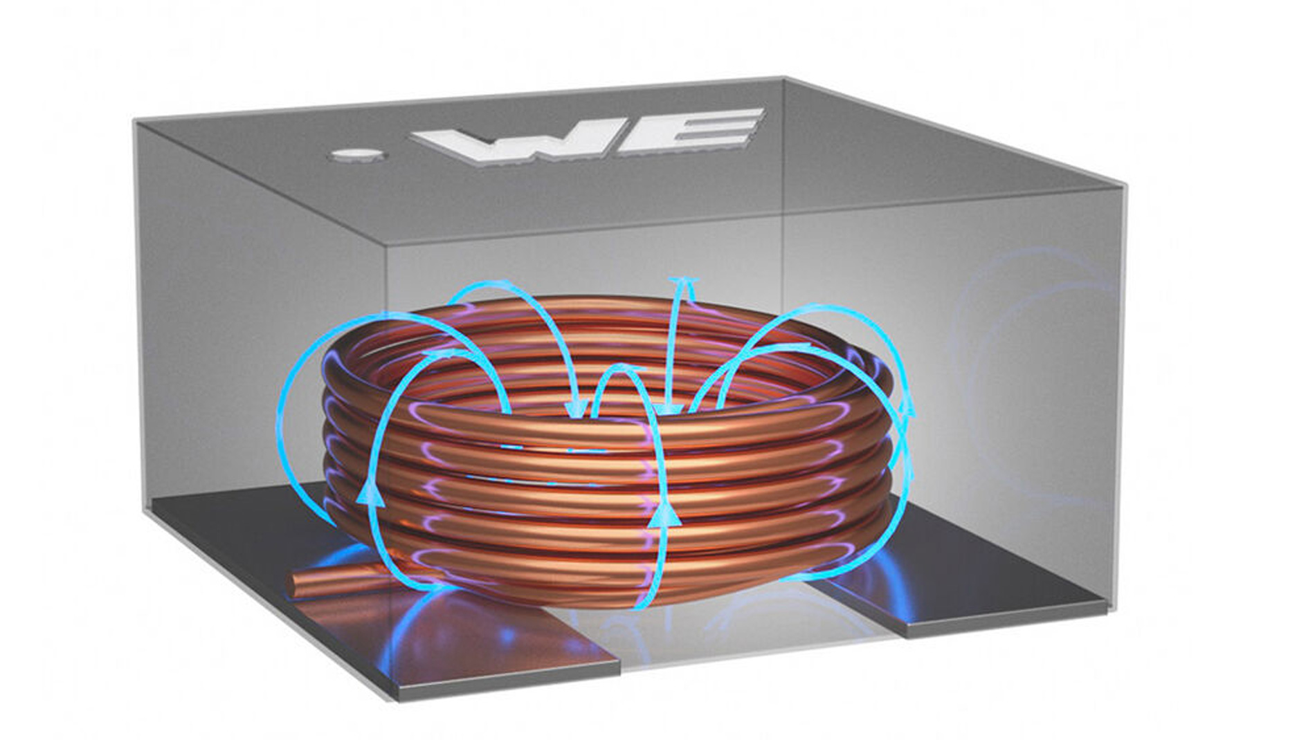
In practice, the start of the coil winding is usually connected to the switching node of the switching regulator – the component has a marking for this purpose. This reduces coupling effects and interference originating from the switching node, which are shielded by the winding. This shielding effect is only possible thanks to the optimized wire geometry of the WE-MXGA, which is based on round wire. Products based on flat wire, which are commonly found on the market, do not have this effect (Figure 2).
The new WE-MXGA series is currently available in 4.1 x 4.1 x 2.1 mm3 and 5.4 x 5.4 x 3.1 mm3 dimensions and is being continuously expanded (Figure 3).
Losses in storage chokes
The losses in a storage choke consist of core material losses and winding losses. The loss mechanisms are described in detail in Würth Elektronik’s AppNote ANP031 and summarized in excerpts below. The winding losses themselves can be divided into DC losses, which are significantly influenced by the DC resistance RDC of the winding (Equation 1), and AC losses RAC of the winding, which result from the skin and proximity effects.
P = I2 · RDC (Equation 1)
There are several methods for determining the AC losses of the winding, e.g., the Dowell, Ferreira, or Nan/Sullivan methods.
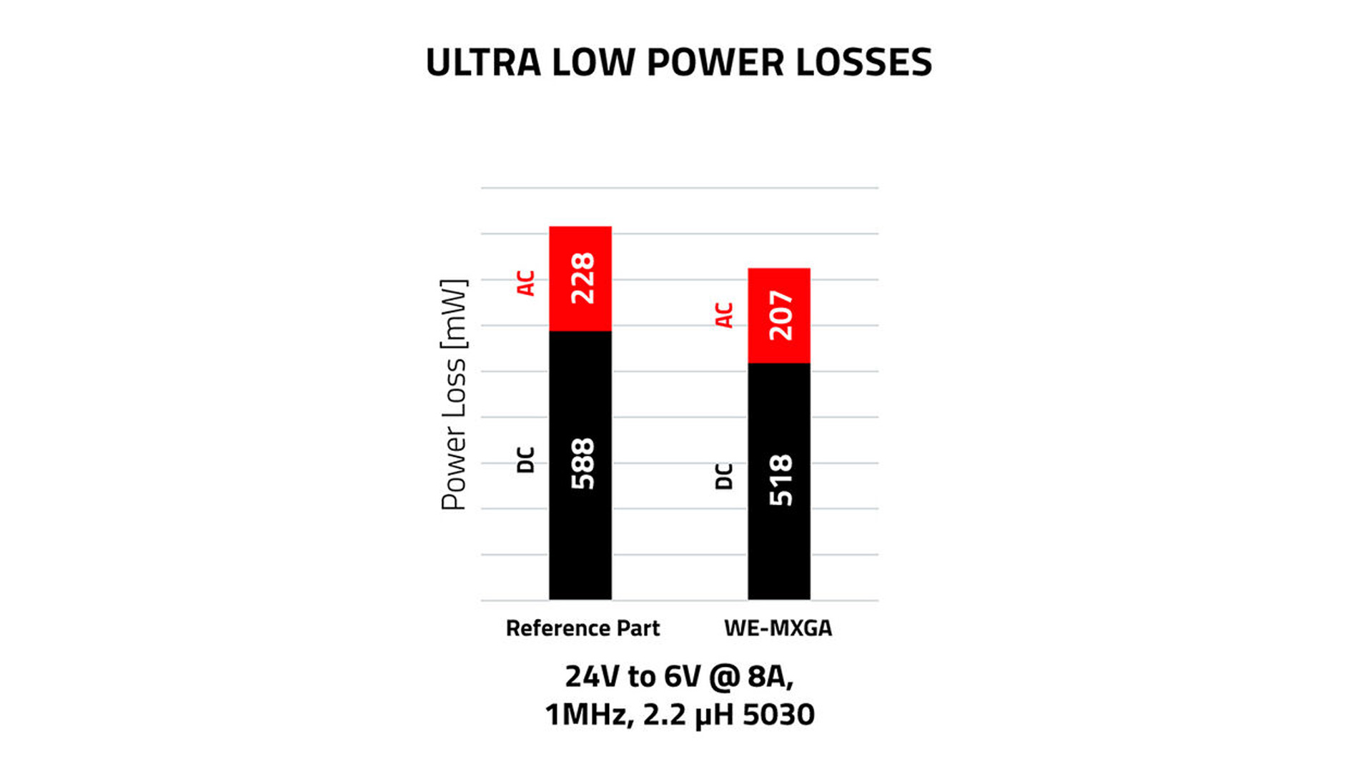
The significance of these losses in modern switching regulators can be determined using a simple setup and measuring the corresponding losses. A step-down regulator with an input voltage of 24 V is used as an example. A voltage of 6 V is available at the output with a current of 8 A. The clock frequency is 1 MHz. In the comparison in Figure 4, a storage inductor with 2.2 µH from the WE-MXGA 5030 series was measured and compared with a storage inductor of the same form factor. It is clear to see that both the AC losses and the DC losses of the WE-MXGA are lower than those of the competing products. In switching regulators, the coil is one of the most important components. Therefore, accurately determining losses and heating is a critical step in selecting the right component. To predict heating, the AC losses must first be accurately determined.
One approach would be to use Steinmetz models, which offer an acceptable approximation, especially for sinusoidal excitation and a duty cycle of 50 percent. However, the Würth Elektronik model provides more accurate results. The AC loss calculator in REDEXPERT includes a model for precisely determining the total AC losses in inductors. This model is based on empirical data obtained from a real-time application setup. First, the total losses of the inductor are divided into AC and DC losses.
The empirical data is recorded using a DC/DC converter. A pulsating voltage is applied to the inductance, whereby the input powerP_in and the output powerP_out are measured. On this basis, P_loss=P_in-P_out and the AC losses of the coil P_AC are separated. This process is measured for a wide range of parameter settings—for example, fluctuations in magnetic modulation, switching frequency, ripple current, etc.—and this empirical data is recorded. This empirical data is used to create the model for calculating the AC losses (Equation 2)
PAC= f(∆I, freq, DC, k1, k2) (Equation 2)
Advantages of the Würth Elektronik AC loss model:
- The empirical data is based on a DC/DC converter application
- Accurate determination of losses for any given duty cycle
- Accurate over a wide frequency range (10 kHz to 10 MHz)
- Takes into account even the smallest changes in core material and winding structure
- Valid for components with more than one material used
- Accurate determination of losses in components with iron powder and metal alloys
- Valid for any core design and winding structure
- Also includes AC winding losses
The Würth Elektronik model has been extensively validated and compared with existing models and measured data. AC losses for various materials such as WE Superflux, iron powder, NiZn, MnZn, etc. were measured over a wide range of duty cycles and frequencies and compared with theoretical models (Figure 5). The diagrams show the core losses determined using the Steinmetz power equation (Pst), modified Steinmetz equation (Pmse), and generalized Steinmetz equation (Pgse). “REDEXPERT” indicates the AC loss calculated using the AC loss model from Würth Elektronik. “Real” is the measured AC loss.
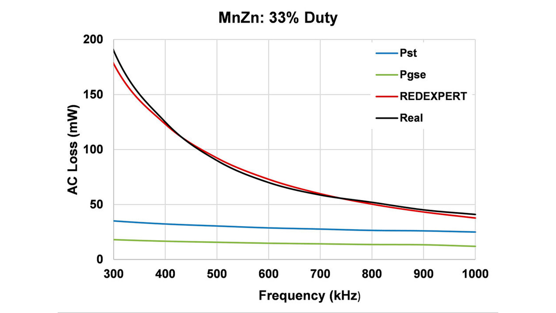
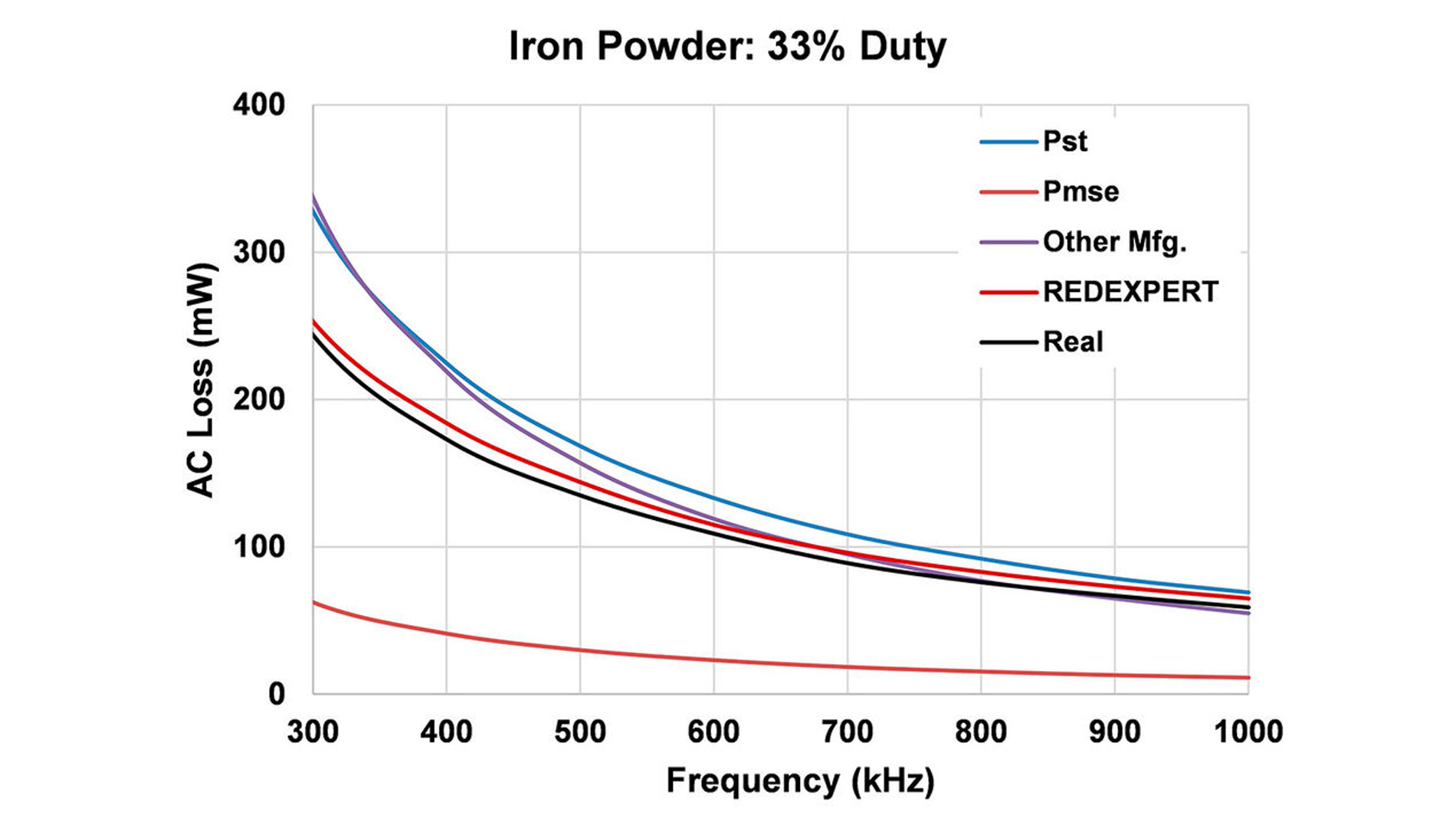
Figure 5: AC losses for MnZn and iron powder core materials and a duty cycle of 33 percent according to various Steinmetz models, simulated with REDEXPERT and measured in real life
Selecting WE-MXGA with REDEXPERT
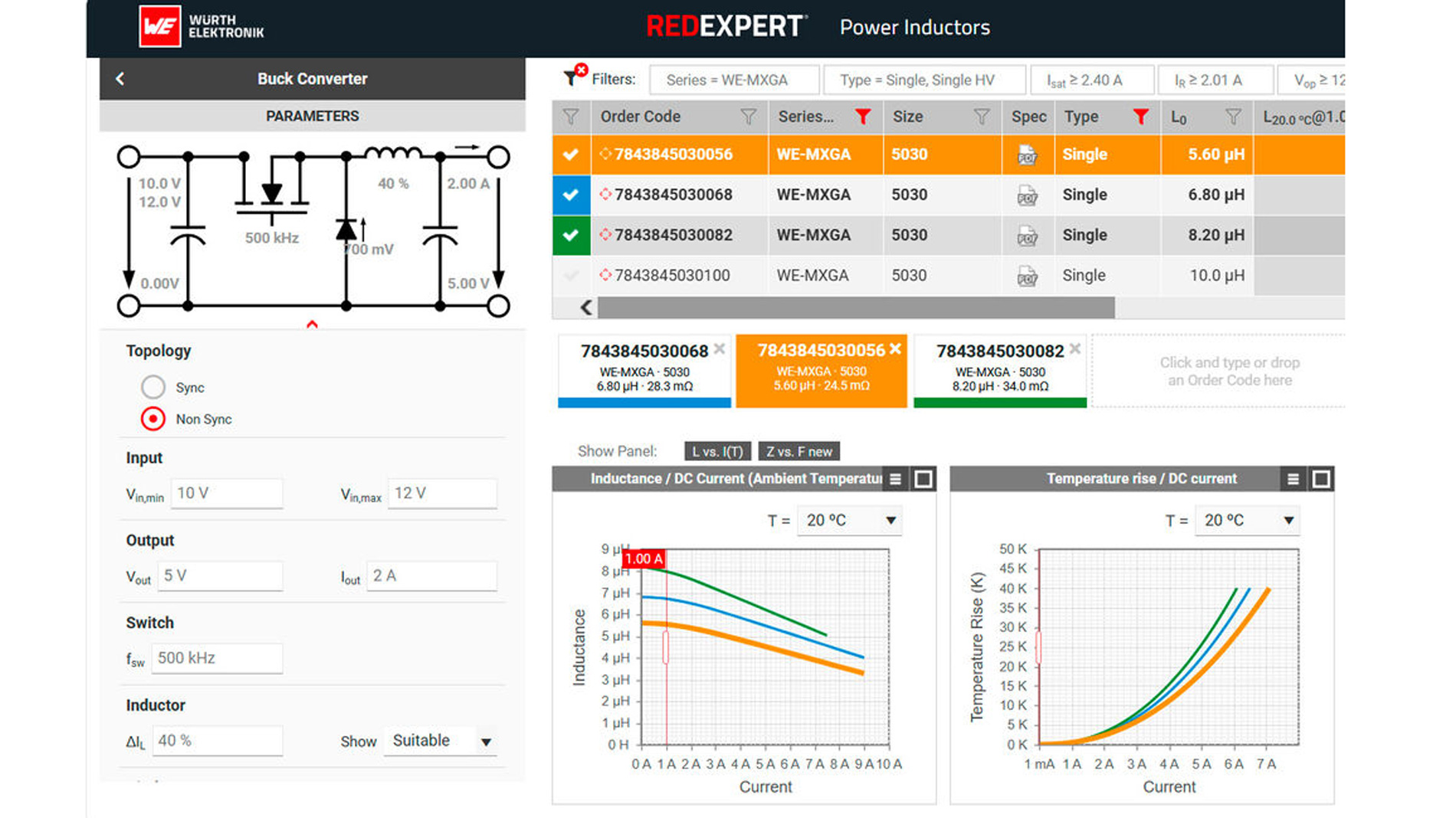
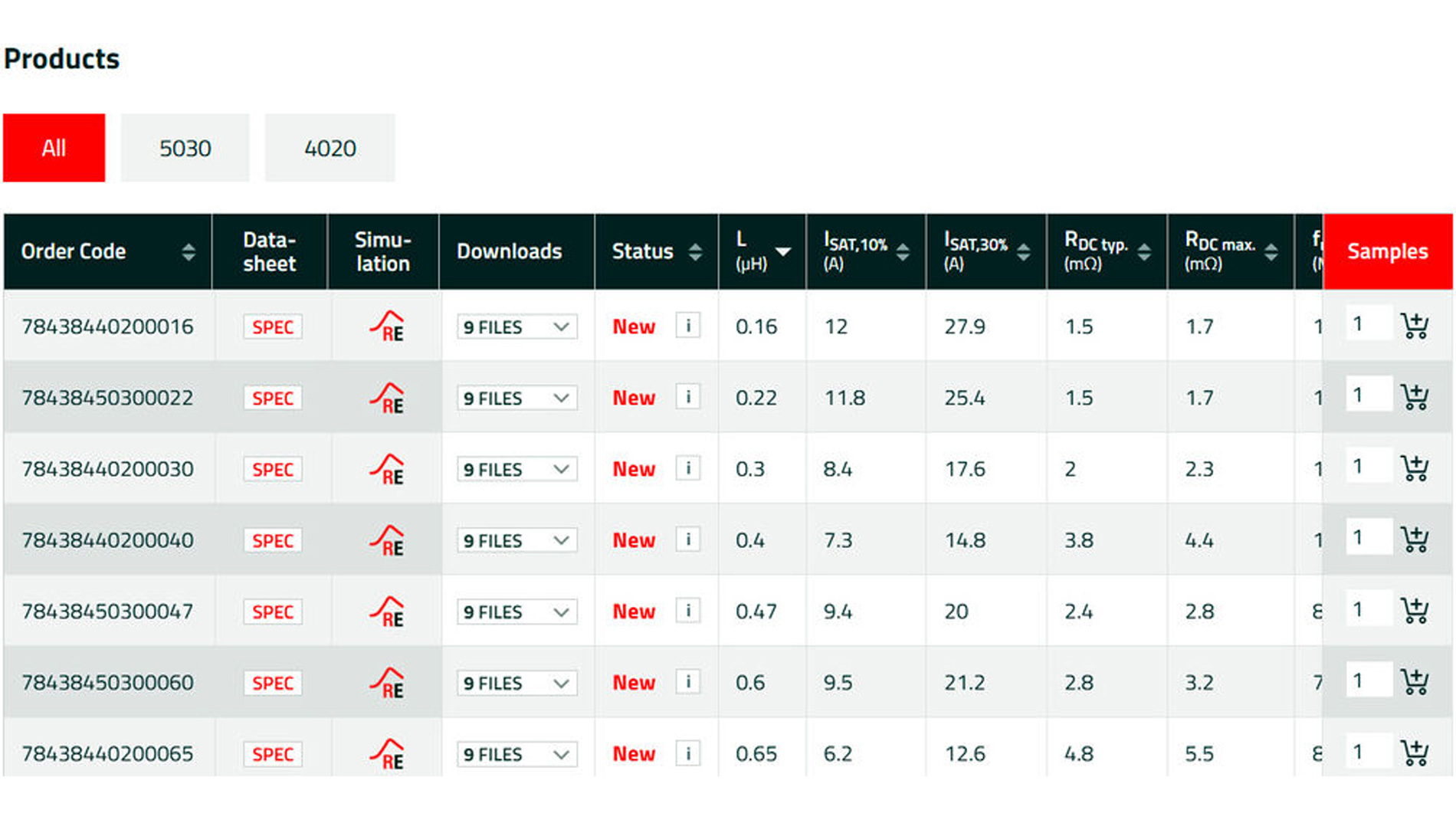
With their innovative core material and sophisticated design, WE-MXGA power inductors are designed for maximum performance and efficiency in the smallest possible space, making them perfect for demonstrating the AC loss calculator. For energy-efficient switching regulators, the best way to select the right WE-MXGA storage choke is to use REDEXPERT (Figure 6), the online design platform from Würth Elektronik. It incorporates the world’s most accurate AC loss model, which achieves a very high degree of accuracy over a wide range of values for the parameters frequency, ripple current, and duty cycle. In addition, REDEXPERT suggests suitable products as soon as the required parameters for a customer application have been entered.
The Würth Elektronik rated current calculator, which can also be found in REDEXPERT, now also supports the selection of the right product. It includes a thermal model of each inductor, also based on measurement data, to determine the rated current according to the PCB dimensions for each specific application. An explanation of the thermal behavior of power chokes can be found in App Note ANP096.